
...
| Sv translation | |||||||||||||||||||||||||||||||||||||||||||||||||||||||||||||||||||||||
|---|---|---|---|---|---|---|---|---|---|---|---|---|---|---|---|---|---|---|---|---|---|---|---|---|---|---|---|---|---|---|---|---|---|---|---|---|---|---|---|---|---|---|---|---|---|---|---|---|---|---|---|---|---|---|---|---|---|---|---|---|---|---|---|---|---|---|---|---|---|---|---|
| |||||||||||||||||||||||||||||||||||||||||||||||||||||||||||||||||||||||
Test File Downloaduart file download :uart Basic Equipment Information
I. Basic Power Supply Test1. Power Interface Function Verification2. Test Environment and Tool Adaptability
3. Basic Test Procedure Specifications1. DC Power Interface Compatibility Test
2. Input Voltage Lower Limit Verification
3. POE Interface Extended Power Supply Test (Optional)
The device can be stably powered by the POE module and operates normally. 二、有线通信接口测试II.Wired Communication Interface Test1.RS232串口测试Serial Port TestRS232 corresponding device node: ttyS3 RS232对应设备节点:ttyS3 (V1.2 版本version) / ttyS4 (V1.4 版本version) 测试准备 Test Preparation: 1.确认串口节点Confirm the serial port node
2.两分钟回环测试Two-minute Loopback Test
输出示例
Output Example
2.RS485串口测试1.测试目的 验证 RK3588 设备的 RS485 串口(映射为系统设备 2.测试环境 设备 / 工具 | 配置信息 | | |||||||||||||||||||||||||||||||||||||||||||||||||||||||||||||||||||||
| RK3588 设备 | 系统:嵌入式 Linux(如 Armbian) RS485 串口: /dev/ttyS0(波特率 115200、8N1) | ||||||||||||||||||||||||||||||||||||||||||||||||||||||||||||||||||||||
| 电脑端 | 工具:UART Assist(串口调试助手) 硬件:USB 转 RS485 模块(如 CH340+MAX485) | ||||||||||||||||||||||||||||||||||||||||||||||||||||||||||||||||||||||
| 链路 | RS485 接线:RK3588 的 RS485_A 接模块 A、RS485_B 接模块 B、共地(GND) |
| Device / Tool | Configuration Information |
|---|---|
| RK3588 Device | System: Embedded Linux (e.g. Armbian) RS485 Serial Port: /dev/ttyS0 (Baud Rate 115200, 8N1) |
| PC | Tool: UART Assist (Serial Debug Assistant) Hardware: USB to RS485 Module (e.g. CH340+MAX485) |
| Connection | RS485 Wiring: Connect RS485_A of RK3588 to Module A, RS485_B to Module B, Common Ground (GND) |
3. Hardware Wiring
- Connect RK3588 RS485 pins to the USB-to-RS485 module:
- RK3588 RS485_A →
- Module A
- RK3588 RS485_B →
- Module B
- RK3588 GND →
- Module GND (Common ground is required to avoid signal interference)
- Connect the USB-to-RS485 module to the computer's USB port and install the corresponding driver (e.g. CH340 driver).
4. Test Steps
4.测试步骤4.1
电脑端PC-side UART Assist
配置Configuration
打开- Open the UART Assist
- tool and select the serial port corresponding to the USB-to-RS485 adapter (e.g. COM3);
- Configure parameters: Baud rate 115200, Data bits 8, Parity none, Stop bits 1, Flow control none;
- Click "Open Serial Port" to confirm a successful connection.
4.2 Unidirectional Transceiver Test (PC → RK3588)
- Start serial port reception on the RK3588 side:
| 代码块 | ||||
|---|---|---|---|---|
| ||||
# 步骤1:准备测试工具Step 1: Prepare Test Tool # 将uart测试程序上传到设备(如果从Windows传输) Upload the UART test program to the device (if transferring from Windows) adb push C:\Users\Administrator\Desktop\uart ./ # 步骤2:赋予权限 Step 2: Grant Permissions chmod 777 ./uart # 步骤3:执行测试 Step 3: Execute Test # 终端1:接收数据Terminal 1: Receive data cat /dev/ttyS0 # 终端2:运行命令工具配置正确的串口参数 ./uart /dev/ttyS0Terminal 2: Run the command tool to configure correct serial port parameters ./uart /dev/ttyS0 |
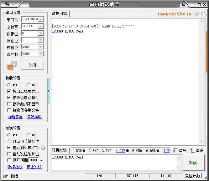
2.Enter test data (e.g. "RK3588 RS485 Test") in UART Assist on the PC side, and click "Send" (as shown in the figure below); 2.电脑端 UART Assist 输入测试数据(如 “RK3588 RS485 Test”),(如下图)点击 “发送”;
3.观察 RK3588 终端1(如下图),若显示接收的测试数据,则单向接收功能正常。Observe RK3588 Terminal 1 (as shown in the figure below). If the received test data is displayed, the unidirectional receiving function is normal.

4.3
单向收发测试(RK3588→电脑)Unidirectional Transceiver Test (RK3588 → PC)
- Keep UART Assist on the PC side in the "Open" state;
- Send test data on the RK3588 side:
| 代码块 | ||||
|---|---|---|---|---|
| ||||
# 步骤1:准备测试工具Step 1: Prepare Test Tool # 将uart测试程序上传到设备(如果从Windows传输)Upload the UART test program to the device (if transferring from Windows) adb push C:\Users\Administrator\Desktop\uart ./ # 步骤2:赋予权限Step 2: Grant Permissions chmod 777 ./uart # 步骤3:执行测试 #发送数据 Step 3: Execute Test # Send data ./uart /dev/ttyS0 # 输入测试文本(如下图) Enter test text (as shown in the figure below) |
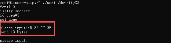
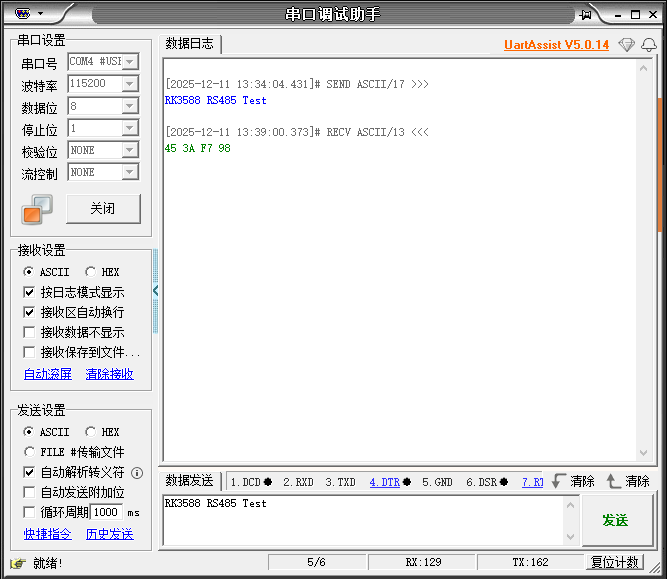
3.
USB接口测试USB Interface Test
1. 设备连接状态识别
通过以下命令确认设备是否接入系统并获取设备节点信息:
Device Connection Status Identification
Use the following commands to confirm whether the device is connected to the system and obtain device node information:
| 代码块 | ||||
|---|---|---|---|---|
| ||||
| 代码块 | ||||
| ||||
# 查看所有块设备,识别USB对应的设备节点(如View all block devices and identify the USB device node (e.g. /dev/sda1)sda1) lsblk # 查看USB设备详细信息,包括控制器和设备ID View detailed USB device information, including controller and device ID lsusb |
lsusb输出中,ID
Result Description: In the output of lsusb, ID 1d6b:0002
对应 USB2stands for USB 2.0
控制器,controller, and ID
1d6b:0003
对应 USB3.0 控制器,可通过设备挂载的总线判断其关联的 USB 版本。stands for USB 3.0 controller. The corresponding USB version can be judged by the bus where the device is mounted.
2.
设备配套USB
版本兼容性Version Compatibility Test
Accurately confirm USB version via device speed parameters. USB2.0 corresponds to High-Speed (480Mbps), USB3.0 corresponds to Super-Speed (5000Mbps). Operations are as follows:
1.Check device speed file
1.查看设备速度文件| 代码块 | ||||
|---|---|---|---|---|
| ||||
# 遍历所有USB设备,输出其传输速度 Traverse all USB devices and output their transfer speed for device in $(ls /sys/bus/usb/devices/); do if [ -f "/sys/bus/usb/devices/$device/speed" ]; then speed=$(cat /sys/bus/usb/devices/$device/speed) echo "Device: $device, Speed: $speed Mbps" fi done |
2.通过详细信息验证Verify through detailed information
| 代码块 | ||||
|---|---|---|---|---|
| ||||
# 查看指定USB设备的详细参数,搜索Speed字段 View detailed parameters of specified USB device, filter Speed field lsusb -v | grep -E "Speed|Device" |
结果说明:输出中 Result description: In the output, Speed: 480Mbit/s 对应 corresponds to USB2.0,0, and Speed: 5000Mbit/s 对应 corresponds to USB3.0.0。
3.
传输性能测试传输速率是Transmission Performance Test
Transmission speed is the core difference between USB2.0
与and USB3.0
的核心差异点,USB2.0 理论速率 480Mbps,USB3.0 理论速率 5Gbps。以下提供两种常用测试方法,分别适用于存储设备和网络类 USB 设备。. The theoretical speed of USB2.0 is 480Mbps, while that of USB3.0 is 5Gbps. Two commonly used test methods are provided below, applicable to USB storage devices and network USB devices respectively.
1. Simple Test: dd Command
The dd command can quickly test read and write speeds for preliminary verification. Mount the USB device first before testing.
1.1 Mount the USB device:
1.1.挂载 USB 设备:
| 代码块 | ||||
|---|---|---|---|---|
| ||||
# 假设通过lsblk确认USB设备节点为Assume the USB device node is /dev/sda1,创建挂载点并挂载sda1 confirmed by lsblk, create mount point and mount mkdir -p /mnt/usb mount /dev/sda1 /mnt/usb |
1 1.2 . 测试顺序写速率:Test sequential write speed:
| 代码块 | ||||
|---|---|---|---|---|
| ||||
# 写入1GB零数据到USB设备,绕过缓存确保结果真实 Write 1GB zero data to the USB device, bypass cache to ensure real results dd if=/dev/zero of=/mnt/usb/testfile bs=1M count=1024 conv=sync oflag=direct |
1.3.测试顺序读速率:Test sequential read speed:
| 代码块 | ||||
|---|---|---|---|---|
| ||||
# 读取USB设备中的测试文件并丢弃,测试读取速度 Read the test file from the USB device and discard it to test the read speed dd if=/mnt/usb/testfile of=/dev/null bs=1M iflag=direct |
1.4.测试后清理临时文件:Clean up temporary files after testing:
| 代码块 | ||||
|---|---|---|---|---|
| ||||
rm /mnt/usb/testfile |
结果说明:命令执行完毕后会显示传输时间和速率,USB2.0 实际写速率通常在 10 - 30MB/s,USB3.0 实际写速率通常在 50 - 150MB/s(受设备本身性能影响)。
2.1.安装 fio:Result Description: After the command is executed, the transfer time and speed will be displayed.
- The actual write speed of USB 2.0 is usually 10 - 30 MB/s.
- The actual write speed of USB 3.0 is usually 50 - 150 MB/s (affected by the performance of the device itself).
2. Professional Test: fio Tool
The fio tool supports complex IO scenario testing with more comprehensive results, suitable for in-depth performance evaluation.
2.1 Install fio:
| 代码块 | ||||
|---|---|---|---|---|
| ||||
# Ubuntu/Debian sudo apt install fio -y |
2.2.Code block for fio 测试命令代码块test commands:
| 代码块 | ||||
|---|---|---|---|---|
| ||||
# 顺序写测试Sequential write test fio -filename=/temp/testfile -direct=1 -ioengine=psync -iodepth 128 -rw=write -bs=1M -size=3G -numjobs=4 -runtime=30 -group_reporting -name=iopstest -time_based=1 # 顺序读测试Sequential read test fio -filename=/temp/testfile -direct=1 -ioengine=psync -iodepth 128 -rw=read -bs=1M -size=3G -numjobs=4 -runtime=30 -group_reporting -name=iopstest -time_based=1 # Random 随机写测试write test fio -filename=/temp/testfile -direct=1 -ioengine=psync -iodepth 128 -rw=randwrite -bs=1M -size=3G -numjobs=4 -runtime=30 -group_reporting -name=iopstest -time_based=1 # Random read 随机读测试test fio -filename=/temp/testfile -direct=1 -ioengine=psync -iodepth 128 -rw=randread -bs=1M -size=3G -numjobs=4 -runtime=30 -group_reporting -name=iopstest -time_based=1 # 随机读写混合测试(默认读写比例 Mixed random read/write test (default read/write ratio 50:50)50) fio -filename=/temp/testfile -direct=1 -ioengine=psync -iodepth 128 -rw=randrw -bs=1M -size=3G -numjobs=4 -runtime=30 -group_reporting -name=iopstest -time_based=1 |
4. Type-
C接口测试C Interface Test
1.
ADB功能测试ADB Function Test
1.1
. ADB基础连接测试测试目的:验证 Type‑C 接口可正常建立 ADB 连接,设备可被 PC 识别。
测试步骤:
1.用 Type‑C 数据线连接待测设备与 PC。
2.设备端开启「开发者选项」→「USB 调试」。
3.PC 端执行 adb devices,检查设备是否被识别。
4.执行 adb shell,验证是否可进入设备命令行。
预期结果:
1.adb devices 输出设备序列号,状态为 device。
2.成功进入设备 shell,无连接超时或权限拒绝。
1.2. ADB 核心指令执行测试
测试目的:验证 ADB 核心指令在 Type‑C 链路下可正常执行。
测试步骤:
1.用文件传输:
执行Basic ADB Connection Test
Test Purpose: Verify that the Type-C interface can establish ADB connection normally and the device can be recognized by PC.
Test Steps:
- Connect the device under test and PC with a Type-C data cable.
- Enable Developer options → USB debugging on the device.
- Run
adb deviceson PC to check if the device is detected. - Run
adb shellto verify access to the device command line.
Expected Results:
adb devicesdisplays the device serial number with the status shown as device.- Successfully enter the device shell without connection timeout or permission denial.
1.2 Core ADB Command Execution Test
Test Purpose: Verify that core ADB commands work properly over the Type-C link.
Test Steps:
- File transmission:
Runadb push test_file /data/
2.设备控制:
执行 adb reboot 重启设备,重启后重新执行 adb devices。
3.日志抓取:
执行- to send files to the device.
Runadb pull /data/test_file ./
- to download files to PC.
- Device control:
Runadb rebootto restart the device, then executeadb devicesagain after reboot. - Log capture:
Run
adb logcat -d > adb_log.txt
- to capture system logs.
Expected Results:
- File transmission completes successfully, and the downloaded file has the same size as the original.
- ADB connection recovers automatically after reboot.
- The log file is not empty and contains valid running logs.
1.3 Type-C Plug & Play and Stability Test
Test Purpose: Verify the stability of ADB connection during Type-C cable plugging, unplugging and shaking.
Test Steps:
- Single plug operation: Plug and unplug the data cable 10 times, and run
adb devicesafter each operation. - Continuous plug operation: Rapidly plug and unplug 20 times with an interval of 1–2 seconds.
- Shake test: Keep the cable connected and shake it gently, then observe the connection status.
Expected Results:
- The device is recognized normally after each operation with no offline status.
- ADB connection remains stable during shaking with no I/O errors.
1.4 High-load Stability Test for Type-C Connection
Test Purpose: Verify the stability of Type-C ADB function under high load.
Test Steps:
- Large file transmission: Push a 1GB file to the device while running
adb logcat. - Concurrent commands: Run
adb push,adb shell topandadb logcatsimultaneously. - Long-duration connection: Maintain ADB connection for 24 hours and run
adb devicesevery hour.
Expected Results:
- ADB connection stays active during large file transmission, and log capture works normally.
- No crash or timeout occurs when running multiple commands; CPU usage ≤ 80%.
- The connection status remains device within 24 hours with no disconnection.
2. Type-C to USB Hub Test
2.1 Device Recognition and Compatibility Test
Prerequisites:
- The development board is powered on and the system boots up completely.
- The Type-C to USB Hub is connected properly.
Operation Steps:
- Insert the Type-C end into the Type-C port of the development board.
- Connect USB devices (USB flash drive, mouse, keyboard) to the USB ports of the Hub one by one.
- Run
lsusbto view the device list. - Check system logs with
dmesg | grep usb.
Expected Results:
- All USB devices are recognized correctly, and corresponding device IDs are shown in the
lsusboutput. - No recognition failures or error messages related to USB devices in system logs.
- The USB flash drive can be mounted and read/written normally; the mouse and keyboard respond properly.
2.2 Data Transfer Speed Test
Prerequisites:
- Same as Section 2.1
- Prepare a 1GB test file named test.img
Operation Steps:
- Connect a USB 3.0 flash drive and mount it to
/mnt/usb. - Run the file copy command:
预期结果:
1.文件传输无失败,拉取文件与原文件大小一致。
2.重启后 ADB 连接可自动恢复。
3.日志文件非空,包含有效运行日志。
1.3. Type‑C 插拔与稳定性测试
测试目的:验证 Type‑C 接口在插拔、晃动等场景下 ADB 连接的稳定性。
测试步骤:
1.单次插拔:插拔数据线 10 次,每次插拔后执行 adb devices。
2.连续插拔:快速插拔 20 次,间隔 1–2 秒。
3.晃动测试:保持连接状态,轻微晃动数据线,观察连接状态。
预期结果:
1.每次插拔均可正常识别设备,无 offline 状态。
2.晃动过程中 ADB 连接不中断,无 IO 错误。
1.4. Type‑C 插拔与稳定性测试
测试目的:验证高负载场景下 Type‑C ADB 功能的稳定性。
测试步骤:
1.大文件传输:推送 1GB 文件至设备,同时执行 adb logcat。
2.多指令并发:同时执行 adb push、adb shell top、adb logcat。
3.长时间连接:保持 ADB 连接 24 小时,每小时执行 adb devices。
预期结果:
1.大文件传输过程中 ADB 不中断,日志抓取正常。
2.多指令并发无卡死或超时,CPU 占用 ≤ 80%。
3.24 小时内连接状态持续为 device,无自动断开。
2.Type-C 转 hub(USB)测试
2.1 设备识别与兼容性测试前置条件:
1.开发板上电正常,系统启动完成
2.Type-C 转 USB Hub 连接正常
操作步骤:
1.将 Type-C 端插入开发板 Type-C 接口
2.将 USB 设备(U 盘、鼠标、键盘)依次插入 Hub 的 USB 口
3.执行命令 lsusb 查看设备列表
4.查看系统日志 dmesg | grep usb
预期结果:
1.所有 USB 设备均能被系统正确识别,lsusb 输出中可见对应设备 ID
2.系统日志无 USB 设备识别失败或报错信息
3.U 盘可正常挂载 / 读写,鼠标 / 键盘可正常响应
2.2 数据传输速率测试
前置条件:
1.同 2.1
2.准备 1GB 测试文件(test.img)
操作步骤:
1.插入 USB3.0 U 盘并挂载到 /mnt/usb
2.执行文件拷贝命令:| 代码块 |
|---|
dd if=/dev/zero of=/mnt/usb/test.img bs=1M count=1024 |
3.记录传输耗时,计算速率:速率 Record the transmission time and calculate the speed: Speed = 1024MB / 耗时(秒)Time (seconds)
4.反向拷贝回开发板,重复测试 3 次
预期结果:
1.USB3.0 模式下传输速率 ≥ 80MB/s(约 640Mbps)
2.USB2.0 模式下传输速率 ≥ 30MB/s(约 240Mbps)
3.无数据丢失、无传输中断、无文件损坏
2.3 供电能力测试
前置条件:
1.同 3.1
2.准备 2.5 英寸移动硬盘(需 5V/0.5A 以上供电)
操作步骤:
1.将移动硬盘插入 Hub 的 USB 口
2.观察硬盘指示灯是否亮起,执行 lsblk 查看设备节点
3.进行大文件读写操作,持续 10 分钟
4.查看系统日志是否有供电不足或设备掉线信息
预期结果:
1.移动硬盘正常启动,系统可识别并读写
2.长时间读写过程中无设备掉线、无数据损坏
3.系统日志无 over-current 或供电相关报错
2.4. 异常场景测试
1.热插拔测试:在数据传输过程中插拔 USB 设备,验证系统稳定性
2.低电压测试:降低开发板供电电压至 4.5V,验证 USB 设备是否正常工作
3.多设备并发测试:同时插入多个 USB 设备,验证 Hub 负载能力
3.Type-C 转 HDMI/DP 输出测试
3.1 视频输出功能测试
前置条件:
1.开发板上电正常,系统启动完成
2.Type-C 转 HDMI/DP 转接器连接正常,显示器通电
操作步骤:
1.将 Type-C 端插入开发板 Type-C 接口,HDMI/DP 端插入显示器
2.执行显示配置命令(Linux:xrandr;Android:系统设置)
3.切换显示输出到 HDMI,设置分辨率为 1080P@60Hz
4.观察显示器画面,检查是否有花屏、黑屏、闪烁
预期结果:
1.显示器自动点亮,显示开发板桌面 / 画面
2.分辨率、刷新率可正常配置,画面清晰无失真
3.无花屏、无黑屏、无闪烁、无延迟
3.2 音视频同步输出测试
前置条件:
1.同 3.1
2.显示器支持 HDMI/DP 音频输出
操作步骤:
1.播放 1080P 测试视频(带音轨)
2.观察画面流畅度,同时监听显示器扬声器
3.检查音画是否同步,有无杂音、断音
预期结果:
1.视频画面流畅,帧率稳定(≥30fps)
2.音画同步,无延迟、无卡顿
3.声音清晰,无杂音、无断音、无爆音
3.3 热插拔测试
前置条件:
同 3.1
操作步骤:
1.先连接 Type-C 转 HDMI/DP,确认显示正常
2.拔掉 HDMI/DP 端,观察系统反应
3.重新插入 HDMI/DP 端,观察系统反应
4.重复热插拔 10 次,记录每次结果
预期结果:
1.拔掉 HDMI/DP 后,系统自动切回板载显示或黑屏(符合设计预期)
2.重新插入后,显示器自动恢复显示,无需手动配置
3.热插拔过程中无系统崩溃、无驱动报错
3.4. 异常场景测试
1.分辨率切换测试:在 720P/1080P/4K 之间切换,验证显示兼容性
2.长时间播放测试:连续播放视频 24 小时,验证稳定性
3.低分辨率输出测试:设置为 480P,验证向下兼容能力
三、显示与视频接口测试
1.HDMI/DP输出测试
1.规格说明:
Copy files back to the development board in reverse direction and repeat the test 3 times.
Expected Results:
- Transmission speed ≥ 80MB/s (about 640Mbps) under USB 3.0 mode.
- Transmission speed ≥ 30MB/s (about 240Mbps) under USB 2.0 mode.
- No data loss, transmission interruption or file corruption.
2.3 Power Supply Capability Test
Prerequisites:
- Same as Section 2.1
- Prepare a 2.5-inch portable hard drive (requiring power supply of 5V/0.5A or above)
Operation Steps:
- Connect the portable hard drive to the USB port of the Hub.
- Check if the hard drive indicator light is on, and run
lsblkto view the device node. - Perform large file read and write operations continuously for 10 minutes.
- Check system logs for warnings about insufficient power or device disconnection.
Expected Results:
- The portable hard drive starts normally and can be recognized, read and written by the system.
- No device disconnection or data corruption during long-duration read and write operations.
- No over-current or power supply related errors in system logs.
2.4 Abnormal Scenario Test
- Hot-plug test: Plug and unplug USB devices during data transmission to verify system stability.
- Low voltage test: Reduce the power supply voltage of the development board to 4.5V and check if USB devices work normally.
- Multi-device concurrency test: Connect multiple USB devices simultaneously to verify the load capacity of the Hub.
3. Type-C to HDMI/DP Output Test
3.1 Video Output Function Test
Prerequisites:
- The development board is powered on and the system boots up completely.
- The Type-C to HDMI/DP adapter is connected properly and the monitor is powered on.
Operation Steps:
- Plug the Type-C end into the Type-C port of the development board, and connect the HDMI/DP end to the monitor.
- Execute display configuration commands (Linux: xrandr; Android: System Settings).
- Switch display output to HDMI and set the resolution to 1080P@60Hz.
- Observe the screen and check for screen distortion, black screen or flickering.
Expected Results:
- The monitor lights up automatically and displays the desktop or screen of the development board.
- Resolution and refresh rate can be configured normally with clear and undistorted images.
- No screen distortion, black screen, flickering or lag.
3.2 Audio and Video Synchronization Test
Prerequisites:
- Same as Section 3.1
- The monitor supports HDMI/DP audio output.
Operation Steps:
- Play a 1080P test video with audio tracks.
- Observe video fluency and listen to sound from the monitor speaker.
- Check audio-video synchronization and verify for noise or audio interruption.
Expected Results:
- The video plays smoothly with stable frame rate (≥30fps).
- Audio and video are synchronized without lag or stutter.
- Sound is clear with no noise, interruption or popping sound.
3.3 Hot-plug Test
Prerequisites:
Same as Section 3.1
Operation Steps:
- Connect the Type-C to HDMI/DP adapter first and confirm normal display.
- Unplug the HDMI/DP end and observe system response.
- Reconnect the HDMI/DP end and observe system response.
- Repeat hot plugging 10 times and record each result.
Expected Results:
- After unplugging HDMI/DP, the system automatically switches back to the onboard display or goes black (in line with design requirements).
- The monitor restores display automatically after reconnection without manual configuration.
- No system crash or driver errors occur during hot plugging.
3.4 Abnormal Scenario Test
- Resolution switching test: Switch among 720P/1080P/4K to verify display compatibility.
- Long-time playback test: Play videos continuously for 24 hours to verify stability.
- Low-resolution output test: Set resolution to 480P to verify downward compatibility.
III. Display and Video Interface Test
1. HDMI/DP Output Test
1. Specification Description:
| Interface | Core Specifications | Key Limitations |
|---|---|---|
| HDMI 2.1 | Single port, supports 8K@30Hz / 4K@60Hz, HDCP 2.3 | Requires HDMI 2.1 certified cable, maximum bandwidth 48Gbps |
| DP 1.4a (4Lane) | Single port, supports 4K@60Hz, HDCP 2.3 | Full 60Hz frame rate available for 4K resolution |
1.Query display interfaces and resolution list
1.显示接口及分辨率列表查询
| 代码块 | ||||
|---|---|---|---|---|
| ||||
# 图形界面(X11)- 直观查看支持的分辨率/刷新率/HDCP状态Graphical Interface (X11) - Intuitively view supported resolutions/refresh rates/HDCP status xrandr --verbose | grep -E "HDMI|DP|3840|7680|HDCP" |
2.音频输出测试步骤(命令行操作)Audio Output Test Steps (Command Line Operation)
| 代码块 | ||||||
|---|---|---|---|---|---|---|
| ||||||
# Step 1: Connect to the device via adb (Ensure debugging mode is enabled on the device)# 步骤1:通过adb连接设备(确保设备已开启调试模式) adb shell # 步骤2:推送测试音频文件到设备(电脑端执行)Step 2: Push the test audio file to the device (Execute on the PC) adb push C:\Users\Administrator\Desktop\test.wav /test.wav # 步骤3:查看设备音频输出列表(确认card编号对应关系) Step 3: Check the device audio output list (Confirm the corresponding card number) aplay -l # 步骤4:HDMI0音频输出测试Step 4: HDMI0 Audio Output Test aplay -D plughw:0,0 /test.wav # 预期现象:HDMI连接的显示设备播放音频 Expected Result: The display device connected via HDMI plays audio # 步骤5:DP1音频输出测试Step 5: DP1 Audio Output Test aplay -D plughw:4,0 /test.wav # 预期现象:DP连接的显示设备播放音频 # Expected Result: The display device connected via DP plays audio |
2. HDMI
输入测试Input Test
1. 测试准备
1.硬件连接:将有效 HDMI 信号源(如笔记本电脑、HDMI 摄像头、机顶盒等)通过标准 HDMI 线连接至开发板的 HDMI IN 接口;
2.信号源配置:确保 HDMI 信号源已开机,且输出分辨率 / 帧率与开发板 HDMI IN 接口兼容(推荐 1920×1080@60Hz,避免非标准分辨率导致识别失败);
3.系统登录:通过 SSH / 串口 / 本地终端登录开发板系统,建议使用具备图形显示权限的用户(如 blueberry)操作。
Test Preparation
- Hardware Connection: Connect a valid HDMI signal source (such as a laptop, HDMI camera, set-top box, etc.) to the HDMI IN interface of the development board using a standard HDMI cable.
- Signal Source Configuration: Ensure the HDMI signal source is powered on, and the output resolution/frame rate is compatible with the development board's HDMI IN interface (1920×1080@60Hz is recommended to avoid recognition failure caused by non-standard resolutions).
- System Login: Log in to the development board system via SSH / Serial Port / Local Terminal. It is recommended to operate with a user with graphics display permissions (e.g., blueberry).
2. HDMI Input Device Node Query and Verification
- View the system video device list
| 代码块 | ||||
|---|---|---|---|---|
| ||||
# 切换到具备图形显示权限的用户(避免权限不足导致设备访问失败) Switch to the user with graphical display permissions (to avoid device access failure due to insufficient permissions) su - blueberry # 列出List all video-related devices under the /dev 目录下所有视频相关设备,确认directory and confirm the device node corresponding to HDMI IN 对应的设备节点 ls -la /dev/video* |
查询结果:Query Results:
| 代码块 | ||||
|---|---|---|---|---|
| ||||
-rw-rw---- 1 root video 4 Dec 2 02:18 /dev/video-dec0 -rw-rw---- 1 root video 4 Dec 2 02:18 /dev/video-enc0 crw-rw----+ 1 root video 81, 0 Dec 2 02:18 /dev/video0 |
2.查询设备详细信息Query device details
| 代码块 | ||||
|---|---|---|---|---|
| ||||
执行命令# Execute command: cat /sys/class/video4linux/video0/name 输出结果:# Output result: stream_hdmirx # Description: stream_hdmirx 说明: stream_hdmirx 表示这是一个视频流 HDMI 接收设备(hdmirx indicates this is a video stream HDMI receiving device (hdmirx = HDMI Receiver)Receiver) |
| Device Node |
|---|
| Device Type |
|---|
| Function Description |
|---|
| Permissions / |
|---|
| Device Numbers |
|---|
| /dev/video0 |
| Character device (starts with c) | HDMI input video capture device (core) | Read/writable by root/video group; major number 81, minor number 0 |
| /dev/video-dec0 |
| Regular file | System video decoding device | Read/writable by root/video |
| group |
| /dev/video-enc0 |
| Regular file | System video encoding device | Read/writable by root/video |
| group |
3.查询设备驱动信息:Query device driver information:
| 代码块 | ||||
|---|---|---|---|---|
| ||||
readlink -f /sys/class/video4linux/video0/device/driver |
3. HDMI
输入视频流播放测试Input Video Stream Playback Test
1.
执行视频播放命令:Execute video playback command:
| 代码块 | ||||
|---|---|---|---|---|
| ||||
# 切换到具备图形显示权限的用户Switch to the user with graphical display permissions su - blueberry # 配置显示环境变量(指定主屏输出),通过 GStreamer 播放 HDMI 输入视频流 Configure display environment variable (specify main screen output), play HDMI input video stream via GStreamer gst-launch-1.0 v4l2src device=/dev/video0 ! videoconvert ! autovideosink |
| 代码块 | ||||
|---|---|---|---|---|
| ||||
Setting pipeline to PAUSED ... # 管道状态:暂停中Pipeline status: Pausing Using mplane plugin for capture # 采集插件:使用mplane(多平面)模式 Capture plugin: Using mplane (multi-planar) mode Pipeline is live and does not need PREROLL ... # 管道状态:已激活,无需预滚动 Pipeline status: Active, no preroll required Pipeline is PREROLLED ... # 管道状态:完成预滚动(数据已就绪) Pipeline status: Preroll completed (data ready) Setting pipeline to PLAYING ... # Pipeline status: 管道状态:播放中Playing New clock: GstSystemClock # 时钟初始化:使用系统时钟同步 |

Clock initialization: Synchronized with system clock |
Output Interpretation
- The video capture plugin (mplane) is loaded successfully.
- The pipeline completes initialization, activation and preroll, and video stream transmission works properly.
- The clock synchronization component (GstSystemClock) runs normally and provides time reference for the video stream.
Display Performance
| Abnormal Phenomenon | Possible Cause | Troubleshooting Methods |
|---|---|---|
| Terminal prompts "No such device" | The node /dev/video0 does not exist | 1. Check if the HDMI IN driver is loaded: lsmod |
grep rk_hdmirx
|
|
echo $DISPLAY 确认值为 :0.0,或切换到本地终端执行命令3.视频硬解码性能测试
1.测试环境(MPP 视频硬解码设备)
基于 Rockchip MPP(Media Process Platform)框架的硬解码工具信息:
Reconnect the HDMI cable to ensure good contact | ||
| No playback window on the display | Incorrect configuration of the DISPLAY environment variable | Run echo $DISPLAY to confirm the value is :0.0, or execute commands in the local terminal |
| Stuttering / distorted image | Incompatible resolution of the signal source | Adjust the output resolution of the HDMI signal source to 1080P@60Hz and test again |
3. Video Hard Decoding Performance Test
1. Test Environment (MPP Video Hard Decoding Device)
Based on the hard decoding tool information of the Rockchip MPP (Media Process Platform) framework:
| Item | Details |
|---|---|
| Tool Name | ppvidedec |
| Tool Version |
ppvidedec| 1.14.4 |
| Dependency Library Path | /usr/lib/aarch64-linux-gnu/gstreamer-1.0/libgstrockchipmpp.so |
| Supported Encoding Formats | HEVC/H. |
| 265, AVC/H. |
| 264, VP8, VP9 | |
| Decoding Type | Hardware-accelerated decoding |
| Maximum Decoding Capability | Supports 8K 10-bit |
| video decoding and 8K 60Hz |
| video output |
Test Steps:2.测试步骤:
 2.1.准备测试视频: Prepare test videos:
| 代码块 | ||||
|---|---|---|---|---|
| ||||
#1.本地测试视频路径: Local test video path:C:\Users\Administrator\Desktop\test_video\4K_60fps.mp4 # 2.通过 ADB 将视频推送至开发板:#2. Push the video to the development board via ADB: adb push "C:\Users\Administrator\Desktop\boot\4K_60fps.mp4" /tmp/ |
2.2.执行硬解码测试(以Perform hardware decoding test (take H.264 格式为例)format as an example)
| 代码块 | ||||
|---|---|---|---|---|
| ||||
# 使用gstUse gst-launch-1.0调用0 to invoke the MPP 硬解码工具,验证解码功能:hardware decoding tool and verify the decoding function: gst-launch-1.0 filesrc location=/tmp/4K_60fps.mp4 ! \ qtdemux ! \ h264parse ! \ mppvideodec ! \ videoconvert ! \ autovideosink |
2.3.测试验证要点
autovideosink |
2.3 Test Verification Points
Video playback status: No abnormalities such as screen tearing, green screen, or stuttering shall occur;
Log information: No errors including decode error, Resource not found, or pipeline doesn't want to preroll shall appear in the terminal output. A normal startup process shall be displayed (example shown below);
Display effect: After executing the playback command, the display interface shall present a complete and clear video image (no image distortion or color distortion caused by decoding exceptions).
Example of normal log output (description)
| 代码块 | ||||
|---|---|---|---|---|
| ||||
Setting pipeline to PAUSED ... Pipeline is PREROLLING ... Pipeline is PREROLLED ... Prerolled, waiting for async message to finish... Setting pipeline to PLAYING ... New clock: GstSystemClock #日志逐行说明: #Setting pipeline to PAUSED ...:GStreamer 管道进入暂停状态,开始初始化音视频解码组件(如 MPP 硬解码器),无报错代表组件加载初始化无异常; #Pipeline is PREROLLING ...:管道进入预滚动阶段,开始读取视频文件并解析码流,为硬解码做数据准备; #Pipeline is PREROLLED ...:预滚动完成,视频码流解析成功,RK3566 的 MPP 硬解码单元已获取有效数据; #Prerolled, waiting for async message to finish...:预滚动完成后等待异步消息确认,是 GStreamer 适配嵌入式设备的正常等待流程,无异常; #Setting... Setting pipeline to PLAYING ...:管道切换至播放状态,硬解码开始输出视频帧至显示设备; #NewNew clock: GstSystemClock:系统时钟同步完成,音视频时序匹配,无卡顿、音画不同步风险。GstSystemClock |
(Note: The attached picture is an example of the interface during normal video playback, which can intuitively verify that the picture is free of distortion and displayed normally.)(注:配图为视频正常播放时的界面示例,可直观验证画面无畸变、显示正常)

3. 开启第二个终端进行cpu占用率监控Open a second terminal to monitor CPU usage
3.1 Operation Steps 3.1操作步骤
| 代码块 | ||||
|---|---|---|---|---|
| ||||
# 操作说明:通过ADB远程执行top命令,查看系统资源占用(取前20行关键信息) adb shell " Step 1: Enter the ADB interactive shell adb shell # Step 2: Execute the top command in the shell (runs normally with TTY environment available) top -n1 | head -20" |
3.2系统状态输出示例(终端执行后输出如下,红框为核心监控项)
-20 |
3.2 Example of system status output (the following content is displayed after terminal execution; core monitoring items are marked in the red box)
| 代码块 | ||||
|---|---|---|---|---|
| ||||
#
top - 06:01:06 up 17:57,  1 user,  load average: 2.10, 2.61, 2.56
Tasks: 276 total,   2 running, 274 sleeping,   0 stopped,   0 zombie
%Cpu(s):  3.8 us,  6.0 sy,  0.0 ni, 90.2 id,  0.0 wa,  0.0 hi,  0.0 si,  0.0 st
MiB Mem :   3899.3 total,     91.5 free,    822.6 used,   2985.2 buff/cache
MiB Swap:      0.0 total,      0.0 free,      0.0 used.   1694.6 avail Mem

    PID USER      PR  NI    VIRT    RES    SHR S  %CPU  %MEM     TIME+ COMMAND
   1981 root      20   0 4747336 266284 215960 R  50.0   6.7 877:37.20 Xorg
   2456 blueber+  20   0 1839264  74872  56884 S  12.5   1.9  60:46.06 xfwm4
   2513 blueber+  20   0  314400  39220  29936 S  12.5   1.0  44:54.98 xfce4-p+
  38043 root      20   0  529528  23188  11316 S  12.5   0.6   0:13.87 gst-lau+
  38263 root      20   0    9048   3400   2712 R   6.2   0.1   0:00.02 top
      1 root      20   0  165012   9932   7220 S   0.0   0.2   5:17.56 systemd
      2 root      20   0       0      0      0 S   0.0   0.0   0:00.45 kthreadd
      3 root       0 -20       0      0      0 I   0.0   0.0   0:00.00 rcu_gp
      4 root       0 -20       0      0      0 I   0.0   0.0   0:00.00 rcu_par+
      8 root       0 -20       0      0      0 I   0.0   0.0   0:00.00 mm_perc+
      9 root      20   0       0      0      0 S   0.0   0.0   0:00.00 rcu_tas+
     10 root      20   0       0      0      0 S   0.0   0.0   0:00.00 rcu_tas+
11 root 20 0 0 0 0 S 0.0 0.0 0:04.57 ksoftir+ |
3.3状态分析
3.3 Status Analysis
| Monitoring Item | Result | Description |
|---|---|---|
| Overall CPU Load | User |
| 3.8% + |
| System 6.0% + |
| Idle 90.2% |
3.4测试结论:视频功能播放正常,无卡顿、花屏现象;CPU 占用率低(硬解码加速生效),系统资源负载符合预期。
四、音频接口测试
| Idle ratio exceeds 90%, sufficient CPU resource redundancy; current high-ratio processes are desktop services (Xorg, xfwm4), belonging to basic system load | ||
| Memory Status | Total 3899MB, Used 829MB, Free 2968MB | Sufficient remaining memory, no risk of insufficient memory |
| Key Process CPU Ratio | Desktop Service (Xorg) 50%, Terminal (tilda) 12.5% | When running the video playback process, focus on its % CPU value (usually <10% when hardware decoding takes effect) |
| Memory Usage | Used 829MB, Cache 2864MB | High memory cache ratio ensures efficient system data read/write |
3.4 Test Conclusion: The video plays normally without stuttering or screen tearing. The CPU usage is low (hardware decoding acceleration is effective), and the system resource load meets expectations.
V. Audio Interface Test
| Card No. | Device Name | Hardware Interface | Function Description |
|---|
card编号
设备名称
硬件接口
| 0 | rockchiphdmi0 | HDMI0 |
| Audio output for the first HDMI port | ||
| 1 | rockchipdp0 | DisplayPort0 |
| 1st DisplayPort port (video output only, no audio support) | ||
| 2 | rockchipdp1 | DisplayPort1 |
| 2nd DisplayPort port (video output only, no audio support) | ||
| 4 | rockchipes8388 | ES8388 Codec |
板载音频接口(3.5mm 4 节接口,支持:耳机输出、扬声器输出、MIC 输入)
| Onboard audio interface (3.5mm 4-pin jack, supporting headphone output, speaker output and MIC input) |
1. Test Preparation
1.1 Tools / Files
- PC side: adb (environment variables required)
- Device side: aplay (pre‑installed)
1.2 Hardware Connection
- For HDMI audio test: Connect an HDMI cable between the device’s HDMI port and an audio‑enabled display device (e.g., a monitor with built‑in speakers).
- For onboard audio test: Plug a 3.5 mm headphone into the onboard audio jack.
1.Audio Output Function Verification
1.音频输出功能验证| 代码块 | ||||
|---|---|---|---|---|
| ||||
# 步骤1:通过adb连接设备(确保设备已开启调试模式)Step 1: Connect to the device via ADB (Ensure USB debugging is enabled) adb shell # 步骤2:推送测试音频文件到设备(电脑端执行) Step 2: Push test audio file to the device (Run on PC) adb push C:\Users\Administrator\Desktop\test.wav /test.wav # 步骤3:查看设备音频输出列表(确认card编号对应关系) # Step 3: List audio output devices (Verify corresponding card numbers) aplay -l # 步骤4:HDMI0音频输出测试 Step 4: HDMI0 audio output test aplay -D plughw:0,0 /test.wav # 预期现象:HDMI连接的显示设备播放音频Expected result: Audio plays on the display device connected via HDMI # 步骤5:板载音频(耳机)输出测试 Step 5: Onboard audio (headphone) output test aplay -D plughw:4,0 /test.wav # 预期现象:3.5mm耳机播放音频 # 步骤6:硬件功能验证(正弦波测试,排除文件本身问题) Expected result: Audio plays through the 3.5mm headphone jack # Step 6: Hardware function verification (Sine wave test to exclude file issues) speaker-test -D hw:4,0 -t sine -f 1000 -c 2 -l 2 # 预期现象:耳机输出1000Hz双声道正弦蜂鸣声 |
Expected result: 1000Hz dual-channel sine tone is output from headphones
|
| Test Item | Operation Command | Expected Result |
|---|---|---|
| HDMI0 Audio Output |
测试项
操作命令
预期结果
| aplay -D plughw:0,0 /test.wav |
显示设备正常播放音频
| Audio plays normally on the display device | |
| Onboard Headphone Output | aplay -D plughw:4,0 /test.wav |
耳机正常播放音频
| Audio plays normally through headphones | |
| Hardware Sine Wave Test | speaker-test -D hw:4,0 -t sine -f 1000 -c 2 -l 2 |
| Beep sound is output from headphones |
2.
音频输入功能验证Audio Input Function Verification
- List all audio capture devices
| 代码块 | ||||
|---|---|---|---|---|
| ||||
# 查看系统音频设备列表(重点关注“Capture”(输入)设备)Check the system audio device list (focus on "Capture" (input) devices) arecord -l |
2.典型输出示例Typical Output Example
| 代码块 | ||||
|---|---|---|---|---|
| ||||
**** List of CAPTURE Hardware Devices **** card 3: rockchiphdmiin [rockchip,hdmiin], device 0: rockchip,hdmiin i2s-hifi-0 [rockchip,hdmiin i2s-hifi-0] Subdevices: 1/1 Subdevice #0: subdevice #0 card 4: rockchipes8388 [rockchip-es8388], device 0: dailink-multicodecs ES8323.3-0010-0 [dailink-multicodecs ES8323.3-0010-0] Subdevices: 1/1 Subdevice #0: subdevice #0 |
| Device Type |
|---|
| Key Information & |
|---|
| Purpose |
|---|
| Status |
|---|
| Description | |
|---|---|
| card 3: rockchiphdmiin device 0 | HDMI-IN |
用于采集 HDMI 信号中的音频流
| audio capture card | Corresponds to the HDMI input audio channel of Rockchip chip Used to capture audio stream from HDMI signal | Detected normally (Subdevices: 1/1) |
| card 4: rockchipes8388 device 0 |
| Onboard audio codec chip | ES8388/ES8323 |
用于板载麦克风 / 扬声器的音频采集 / 播放
| is a low-power audio codec Supports audio capture and playback for onboard microphone and speaker | Detected normally (Subdevices: 1/1) |
4.)Recording Test (Real-time Capture + Playback)4.录音测试(实时采集+播放)
| 代码块 | ||||
|---|---|---|---|---|
| ||||
# 功能:实时采集音频输入(hw:4,0)并输出到音频输出(hw:0,0) # 参数说明: # - arecord端: Function: Real-time audio input capture (hw:4,0) and playback to audio output (hw:0,0) # Parameter Description: # - arecord (capture side): # -D hw:4,0: Specify audio input device (adjust based on actual 'arecord -l' output) # -Dr hw:4,0:指定音频输入设备(需根据实际`arecord -l`结果调整) # -r 48000:采样率48000Hz(适配多数音频设备)48000: Sample rate 48000Hz (compatible with most audio devices) # -c 2:立体声采集(若MIC为单声道,可改为 2: Stereo capture (change to -c 1)1 for mono microphone) # -f s16_le:16位小端音频格式(通用兼容格式)le: 16-bit little-endian format (universal compatible format) # -t raw:以原始格式传输(避免文件编码开销) raw: Transmit in raw format (avoid file encoding overhead) # - aplay (playback side): # - aplay端:D hw:0,0: Specify audio output device (e.g. HDMI/onboard speaker) # -D hw:0,0:指定音频输出设备(如HDMI/板载扬声器) # - 其余参数与arecord保持一致(确保格式匹配) Other parameters match arecord (ensure format consistency) # - &:后台运行(避免终端阻塞): Run in background (prevent terminal blocking) arecord -D hw:4,0 -r 48000 -c 2 -f s16_le -t raw | aplay -D hw:0,0 -r 48000 -c 2 -f s16_le -t raw & |
Test Operations and Result Verification
Notes
- If Device or resource busy appears: Run
killall arecord aplayto release occupied audio devices, then retry the test. - No sound output: Verify the device number of the
-Dparameter viaarecord -landaplay -l. - Excessive noise: Change
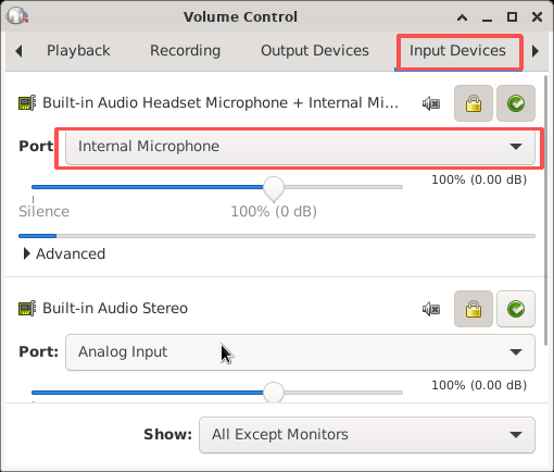
-c 2to-c 1for mono mode, or set the sample rate to 44100. - System audio input configuration: Open system sound settings and go to the Input Devices tab. Select Internal Microphone from the Port drop-down list of the target device to enable the audio input channel properly.
VI. Storage Interface Test
1.M.2
接口测试Interface Test
1. 硬件信息完整性
Hardware Information Integrity
Interface Type: PCIE 2.0 ×1 M.2 M‑Key, 5 Gbps
Hardware Installation: Insert the
M.2 SSD
插入开发板into the M.2
插槽slot on the development board.
2. 基础连接有效性Basic Connection Validity
1.
设备识别验证Device Identification Verification
| 代码块 | ||||
|---|---|---|---|---|
| ||||
# 查看系统是否识别到MCheck whether the system recognizes the M.2 SSD. lsblk |
预期结果:输出中显示 SSD 对应的磁盘设备(如nvme0n1)。Expected Result: The corresponding disk device of the SSD (e.g., nvme0n1) is displayed in the output.
2.磁盘信息读取Disk Information Reading
| 代码块 | ||||
|---|---|---|---|---|
| ||||
# 查看M.2 SSD的详细信息(如容量、接口协议)Check detailed information of the M.2 SSD (e.g., capacity, interface protocol). sudo fdisk -l |
预期结果:显示 SSD 的容量、分区表类型(如 GPT),接口协议为PCIe 3.0 x4。
Expected Result: Display SSD capacity, partition table type (e.g., GPT), PCIe x4 bus and NVMe storage protocol.
3. Read‑Write Performance Test
| 代码块 | ||||
|---|---|---|---|---|
| ||||
# 安装测试工具Install Test Tools sudo apt install hdparm fio # 测试读取性能Test Read Performance sudo hdparm -tT /dev/nvme0n1 # 替换为实际SSD设备名 # 测试随机读写性能(示例:1GB数据)# Replace with your actual SSD device name # Test Random Read/Write Performance (Example: 1GB data) fio --name=ssd-test --filename=/dev/nvme0n1 --size=1G --rw=randrw --bs=4k --numjobs=4 --iodepth=64 --runtime=30 --time_based |
4.
结果判定标准lsblk显示 SSD 设备→识别成功;Judgment Criteria
接口协议:- Device detection: The SSD is displayed via
lsblk→ Detection succeeded. - Interface protocol:
fdisk -l
- shows PCIe 3.0 x4
- → Interface matches.
- Performance requirement: Read speed ≥ 1000MB/s (typical value for PCIe 3.0 SSD
- ) → Performance normal.
2.
SATA接口测试SATA Interface Test
1.硬件连接说明
通过标准 7Pin SATA3.0 接口连接硬盘,SATA 电源支持 5V 2A 输出
2.1 Hardware Connection Description
Connect the hard drive via standard 7-pin SATA 3.0 interface. The SATA power supply supports 5V 2A output.
2.2 Hard Drive Detection & Health Check2.硬盘识别与健康状态检测
| 代码块 | ||||
|---|---|---|---|---|
| ||||
# 查看硬盘信息及SMART健康状态View hard drive information and SMART status fdisk -l #更新软件源(可选,避免安装失败)# Update software sources (optional, to avoid installation failure) apt update # 若提示权限不足,先提权(已 root 可跳过) Elevate privileges if permission denied (skip if already root) # sudo apt update #安装# Install smartmontools apt install -y smartmontools # 注:Note: /dev/sda为实际识别的SATA设备节点,需根据系统显示调整 sda is the actual SATA device node, adjust according to system output smartctl -a /dev/sda |
Test Result Verification
- Device detection:
fdisk -l
smartctl -a 输出中- shall display the capacity and partition information of the SATA hard drive.
- SMART health status: The item SMART overall-health self-assessment test result
PASSED(如图中红框标注项)。- in
smartctl -aoutput shall show PASSED.
VII. Wireless Communication Module Test
六、无线通信模块测试1.
WIFI测试Wi‑Fi Test
1.
硬件规格符合性WiFi 型号:AP6275P,支持Hardware Specification Compliance
WiFi Model: AP6275P. It supports Wi-Fi 6 (IEEE
WiFi6(IEEE802.11a/b/g/n/ac/ax
MIMO),双发双收。2.基础连接稳定性MIMO) with 2T2R (2 Transmit, 2 Receive).
2. Basic Connection Stability
1. 启动NetworkManager服务Start the NetworkManager Service
| 代码块 | ||||
|---|---|---|---|---|
| ||||
sudo systemctl start NetworkManager |
2.扫描并连接WiFi网络Scan and connect to Wi‑Fi networks
| 代码块 | ||||
|---|---|---|---|---|
| ||||
sudo nmcli dev wifi rescan # 重新扫描WiFi网络 sudo nmcli dev wifi list # 查看可用WiFi列表(可选) sudo nmcli dev wifi connect "WiFi名称" password "WiFi密码" ifname wlan1 |
3.网络连通性测试Network Connectivity Test
| 代码块 | ||||
|---|---|---|---|---|
| ||||
ping www.baidu.com |
4.示例命令Sample Commands
| 代码块 | ||||
|---|---|---|---|---|
| ||||
sudo nmcli dev wifi connect "Hi nova 9 Pro" password "12345678" ifname wlan1 |
3. Wi-Fi
网络Network TCP/UDP
协议性能测试Protocol Performance Test
1. 环境准备:
两台测试设备(如开发板 + PC),确保处于同一网络(WiFi / 以太网);
安装 Iperf3Environment Preparation:
Two test devices (e.g., development board + PC), ensure they are on the same network (Wi-Fi/Ethernet);
Install Iperf3
3.Wi-Fi 网络| 代码块 | ||||
|---|---|---|---|---|
| ||||
# Debian/Ubuntu sudo apt install iperf3 |
2. 角色定义:
服务端(Server):接收数据的设备;
客户端(Client):发送数据的设备。
Role Definition Server: Device receiving data
Client: Device sending data
3. TCP 带宽测试(常用)
步骤 1:启动服务端Bandwidth Test (Commonly Used)
Step 1: Start the server
| 代码块 | ||||
|---|---|---|---|---|
| ||||
# 服务端默认监听5201端口The server listens on port 5201 by default iperf3 -s |
| 代码块 | ||||
|---|---|---|---|---|
| ||||
# 测试TCP带宽(持续10秒,默认)Test TCP bandwidth (default duration: 10 seconds) iperf3 -c [服务端IPServer IP] |
| 代码块 | ||||
|---|---|---|---|---|
| ||||
# 测试30秒,每2秒输出一次实时数据 Test for 30 seconds, output real-time data every 2 seconds iperf3 -c [服务端IPServer IP] -t 30 -i 2 # 测试双向带宽(服务端/客户端互传) Test bidirectional bandwidth (simultaneous upload and download) iperf3 -c [服务端IPServer IP] -d |
4. UDP 丢包 Packet Loss / 延迟测试Latency Test
| 代码块 | ||||
|---|---|---|---|---|
| ||||
iperf3 -s |
| 代码块 | ||||
|---|---|---|---|---|
| ||||
# 测试UDP(指定带宽100Mbps)Test UDP with specified bandwidth 100Mbps iperf3 -c [服务端IPServer IP] -u -b 100M |
5. 结果解读(示例)Result Interpretation (Examples)
TCP 测试结果Test Result
| 代码块 | ||||
|---|---|---|---|---|
| ||||
[ 5] local 192.168.1.10 port 5001 connected to 192.168.1.20 port 5201 [ ID] Interval Transfer Bitrate [ 5] 0.00-10.00 sec 1.10 GBytes 943 Mbits/sec # 实际带宽:943Mbps Actual bandwidth: 943Mbps |
UDP Test ResultUDP测试结果
| 代码块 | ||||
|---|---|---|---|---|
| ||||
[ 5] local 192.168.1.10 port 5001 connected to 192.168.1.20 port 5201 [ ID] Interval Transfer Bitrate Jitter Lost/Total Datagrams [ 5] 0.00-10.00 sec 119 MBytes 100 Mbits/sec 0.035 ms 0/85000 (0%) # 丢包率:0% |
6.常见场景测试Common‑Scenario Tests
| Test Objective |
|---|
| Command Example | |
|---|---|
| Long connection stability (1 hour) | iperf3 -c [IP] -t 3600 |
| Multi-thread concurrent test | iperf3 -c [IP] -P 4 (4 |
| threads) | |
| Bandwidth limit test | iperf3 -c [IP] -b 500M |
| (limited to 500Mbps) |
1.
硬件说明Hardware Description
AP6256 is a Wi‑Fi 5 + Bluetooth dual‑mode module launched by AMPAK, supporting Bluetooth 5.2.
2. Enter Bluetooth Command Mode
2.进入蓝牙命令模式
| 代码块 | ||||
|---|---|---|---|---|
| ||||
# 通过adb连接设备 Connect to the device via ADB adb shell # 启动蓝牙控制工具 Launch the Bluetooth control utility sudo bluetoothctl |
3.扫描并连接蓝牙设备Scan and Connect Bluetooth Devices
| 代码块 | ||||
|---|---|---|---|---|
| ||||
scan on # Enable Bluetooth scanning (press Ctrl+C to # 开启蓝牙扫描(按Ctrl+C停止扫描)stop scanning) trust [设备MAC地址]Device MAC Address] # Trust the # 信任目标设备target device pair [设备MAC地址]Device MAC Address] # Pair with the # 配对目标设备target device connect [设备MAC地址]Device MAC Address] # Connect to the target # 连接目标设备device |
4.操作示例Operation Example
| 代码块 | ||||
|---|---|---|---|---|
| ||||
# 扫描后,对MAC为7C Perform operations on the device with MAC 7C:B4:37:11:5B:83的设备执行操作:5B:83 after scanning trust 7C:B4:37:11:5B:83 pair 7C:B4:37:11:5B:83 connect 7C:B4:37:11:5B:83 |
3.
4G模块测试4G Module Test
验证 4G 模块对应的Verify the startup, auto-start configuration and network connectivity of the quectel.service服务的启动、自启配置及网络连通性。 for the 4G module。
1.检查初始状态Check Initial Status
| 代码块 | ||||
|---|---|---|---|---|
| ||||
# 查看服务当前状态Check current service status systemctl status quectel.service # 检查开机自启配置 Check auto-start configuration systemctl is-enabled quectel.service |
预期结果
服务未运行,开机自启未设置Expected Result
The service is inactive and auto-start is disabled.
2. 启动服务Start the Service
| 代码块 | ||||
|---|---|---|---|---|
| ||||
# 启动quectel服务Start quectel service systemctl start quectel.service # Verify service 验证服务状态status systemctl status quectel.service |
预期结果
服务状态显示为 Expected Result
The service status shows active (running).
3.设置开机自启Configure Auto-Start
| 代码块 | ||||
|---|---|---|---|---|
| ||||
# 配置服务开机自启 Enable service auto-start on boot systemctl enable quectel.service # 验证自启配置 # Verify auto-start setting systemctl is-enabled quectel.service |
预期结果
自启配置返回 enabledExpected Result
The command returns enabled.
4. 重启验证Reboot Verification
| 代码块 | ||||
|---|---|---|---|---|
| ||||
# 重启设备Reboot the device reboot # 重启后检查服务状态 Check service status after reboot systemctl status quectel.service |
预期结果
设备重启后,服务自动运行,状态显示为| 代码块 | ||||
|---|---|---|---|---|
| ||||
# 检查4G模块网络接口(以eth0为例,实际需根据模块接口调整)Check 4G network interface (take eth0 as example, adjust according to actual interface) ifconfig -a # 测试网络连通性(ping公网地址) Test network connectivity by pinging public address ping -c 5 8.8.8.8 |
预期结果
4G网络接口正常获取 IP;
ping 测试成功,返回类似如下结果(无丢包):Expected Result
- The 4G interface obtains a valid IP address normally.
- Ping test succeeds with no packet loss, sample output as below:
| 代码块 | ||||
|---|---|---|---|---|
| ||||
PING 8.8.8.8 (8.8.8.8) 56(84) bytes of data. 64 bytes from 8.8.8.8: icmp_seq=1 ttl=109 time=60 ms 64 bytes from 8.8.8.8: icmp_seq=2 ttl=109 time=60 ms 64 bytes from 8.8.8.8: icmp_seq=3 ttl=109 time=60 ms 64 bytes from 8.8.8.8: icmp_seq=4 ttl=109 time=60 ms 64 bytes from 8.8.8.8: icmp_seq=5 ttl=109 time=60 ms |
4.
SIM卡功能验证SIM Card Function Verification
1. 测试准备
系统:确保quectel.service服务处于Test Preparation
- Hardware: Fully tested 4G module and device with target 4G SIM card inserted.
- System: Ensure
quectel.serviceis inactive (running)
- state.
2.
SIM卡网络状态SIM Card Network Status
| 代码块 | ||||
|---|---|---|---|---|
| ||||
# 步骤1:查看wwan0接口的链路状态(确认接口是否激活) Step 1: Check link status of wwan0 interface ip link show wwan0 # 步骤2:查看wwan0的IP地址信息(确认网络是否获取到地址) Step 2: Check IP address of wwan0 interface ip addr show wwan0 # 步骤3:测试SIM网络的外部连通性(指定从wwan0接口发起请求) Step 3: Test external network connectivity via wwan0 ping -c 4 -I wwan0 www.baidu.com |
3. 结果说明Result Description步骤 1 输出中,若wwan0状态为
- Step 1: Status
UP,LOWER_UP
步骤 2 输出中,若wwan0存在inet开头的 IP 地址,说明网络已成功分配地址;
- means the interface is activated.
- Step 2: An address starting with
inetindicates the interface has obtained an IP address successfully. - Step 3: Output starting with
64 bytes from xxx.xxx.xxx.xxx
- means the SIM network works normally.