
...
| Sv translation |
|---|
...
|
...
|
...
|
...
|
...
|
二、端口描述
1.Debug 端口
...
RP01-RK3588S2 Debug 端口 Pin脚定义
...
Pin脚编号
...
Pin 定义
...
定义说明
...
1
...
RXD
...
串口接收
...
2
...
TXD
...
串口发送
...
3
...
GND
...
电源地
2. Recovery 按键
...
3 .Maskrom 按键
...
4. Power 按键
...
5 .Reset 按键
...
6 .GPIO 端口
...
使用时请注意端口电平一致,电平电压不一样会损坏CPU。
...
RP01-RK3588S2 GPIO Pin脚定义
...
功能4
...
功能3
...
功能2
...
功能1
...
电平
...
GPIO
...
Pin脚编号
...
GPIO
...
电平
...
功能1
...
扩展功能2
...
扩展功能3
...
3V3
...
1
...
2
...
5V0
...
3V3
...
3
...
4
...
5V0
...
GND
...
5
...
6
...
GND
...
GND
...
7
...
8
...
GND
...
PWM13_M2
...
SPDIF1_TX_M0
...
I2C5_SDA_M3
...
UART1_RX_M1
...
3.3V
...
GPIO1_B7
...
9
...
10
...
GPIO1_C1
...
3.3V
...
UART3_TX_M0
...
I2C3_SCL_M0
...
SPI4_MISO_M0
...
MIPI_CAM1_CLK_M0
...
SPDIF0_TX_M0
...
I2C5_SCL_M3
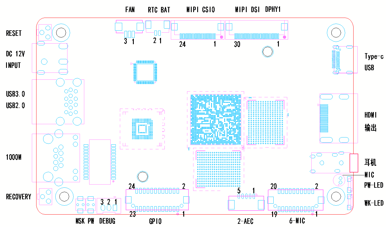
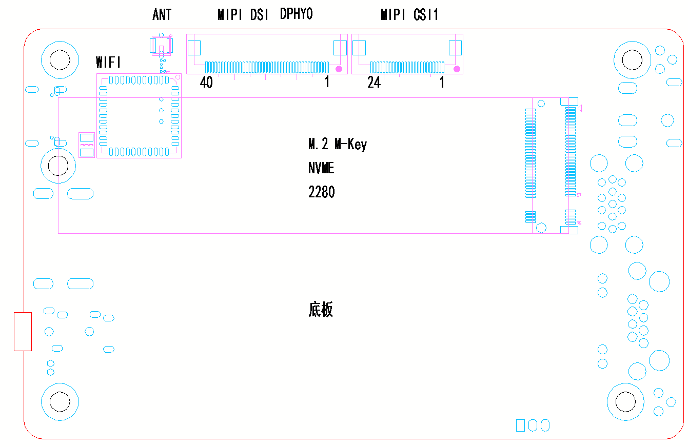
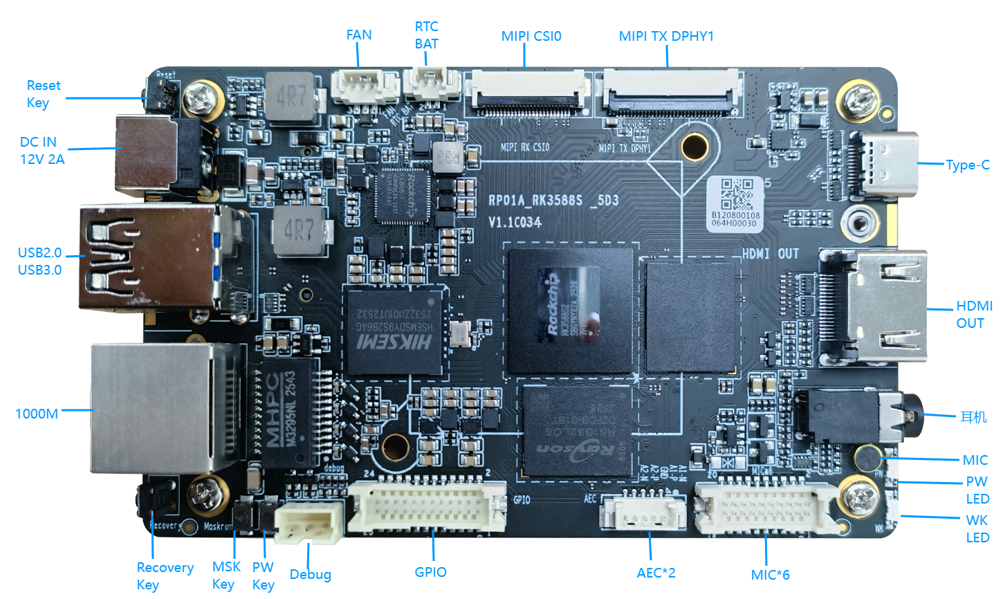
一、接口示意图
二、端口描述1.Debug 端口
2. Recovery 按键
3 .Maskrom 按键
4. Power 按键
5 .Reset 按键
6 .GPIO 端口
使用时请注意端口电平一致,电平电压不一样会损坏CPU。
| ||||||||||||||||||||||||||||||||||||||||||||||||||||||||||||||||||||||||||||||||||||||||||||


...
|
...
11
...
12
...
GPIO1_C0
...
3.3V
...
UART3_RX_M0
...
I2C3_SDA_M0
...
SPI4_MOSI_M0
|
...
SPI0_CS1_M2
...
|
...
13
...
14
|
...
|
...
|
...
15
...
16
...
GPIO1_C4
...
1.8V
|
...
|
...
I2S1_SDO2
|
...
|
...
17
...
18
...
GPIO1_C6
...
1.8V
|
...
|
...
19
...
20
...
GPIO0_A4
...
|
...
21
...
22
...
GPIO0_D3
...
|
...
|
...
23
...
24
...
GPIO0_D5
...
1.8V
7. 6-MIC 输入口
6-MIC 输入口 采用的是1.25MM 2*10P 板对线 wafer 连接器,接口定义如下:
...
RP01-RK3588S2 6-MIC输入 Pin脚定义
...
定义说明
...
Pin 定义
...
Pin脚编号
...
Pin 定义
...
定义说明
...
MIC1正极
...
MIC1+
...
1
...
2
...
MIC2+
...
MIC2正极
...
MIC1负极
...
MIC1-
...
3
...
4
...
MIC2-
...
MIC2负极
...
模拟地
...
AGND
...
5
...
6
...
AGND
...
模拟地
...
MIC3正极
...
MIC3+
...
7
...
8
...
MIC4+
...
MIC4正极
...
MIC3负极
...
MIC3-
...
9
...
10
...
MIC4-
7. 6-MIC 输入口6-MIC 输入口 采用的是1.25MM 2*10P 板对线 wafer 连接器,接口定义如下:
| |||||||||||||||||||||||||||||||||||||||||||||||||||||||||||||||||||||||||||||||||||||||||||||||
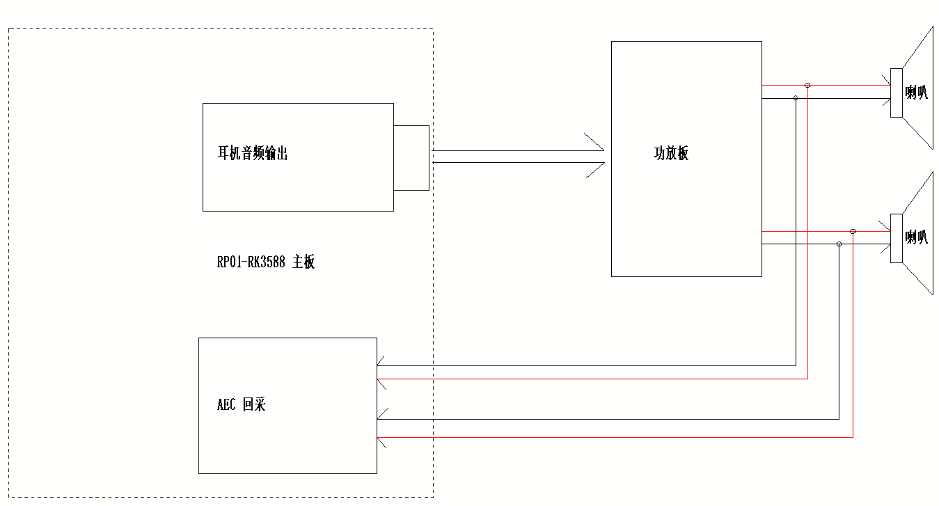
8. 2-AEC 输入端口
AEC回采 框图 | ||||||||||||||||||||||||||||||||||||||||||||||||||||
...
10. 内置MIC
11. MIPI DSI DPHY1 接口
12. MIPI SCI0 接口
| ||||||||||||||||||||||||||||||||||||||||||||||||||||||||||||||||||||||||||||||||||||||||||||||||||||||||||||||||||||||||||||||||||||||||||||||||||||||||||||||||||
...
13. MIPI DSI DPHY0 接口
...
由于此板可以同时支持RK3588S和RK3588S2,区别在于MIPI RX 接口,需要在软件中调整RX链路就可以了。 链路对比如下:
13. MIPI DSI DPHY0 接口
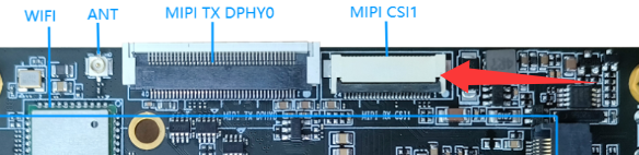
14. MIPI CSI1 接口
15. Fan 接口
16. M.2 M-Key PCIE2.0
17. 以太网
18. Type-c USB
19. USB3.0&USB2.0
20. HDMI输出
21. RTC
22. 电源输入接口
1 | ||||||||||||||||||||||||||||||||||||||||||||||||||||||||||||||||||||||||||||||||||||||||||||||||||||||||||||||||||||||||||||||||||||||||||||||||||||||||||||||||||||||||||||||||||||||||||||||||||||||||||

| Sv translation | |||||||||||||||||||||||||||||||||||||||||||||||||||||||||||||||||||||||||||||||||||||||||||||||||||||||||||||||||||||||||||||||||||||||||||||||||||||||||||||||||||||||||||||||||||||||||||||||||||||||||||||||||||||||||||||||||||||||||||||||||||||||||||||||||||||||||||||||||||||||||||||||||||||||||||||||||||||||||||||||||||||||||||||||||||||||||||||||||||||||||||||||||||||||||||||||||||||||||||||||||||||||||||||||||||||||||||||||||||||||||||||||||||||||||||||||||||||||||||||||||||||||||||||||||||||||||||||||||||||||||
|---|---|---|---|---|---|---|---|---|---|---|---|---|---|---|---|---|---|---|---|---|---|---|---|---|---|---|---|---|---|---|---|---|---|---|---|---|---|---|---|---|---|---|---|---|---|---|---|---|---|---|---|---|---|---|---|---|---|---|---|---|---|---|---|---|---|---|---|---|---|---|---|---|---|---|---|---|---|---|---|---|---|---|---|---|---|---|---|---|---|---|---|---|---|---|---|---|---|---|---|---|---|---|---|---|---|---|---|---|---|---|---|---|---|---|---|---|---|---|---|---|---|---|---|---|---|---|---|---|---|---|---|---|---|---|---|---|---|---|---|---|---|---|---|---|---|---|---|---|---|---|---|---|---|---|---|---|---|---|---|---|---|---|---|---|---|---|---|---|---|---|---|---|---|---|---|---|---|---|---|---|---|---|---|---|---|---|---|---|---|---|---|---|---|---|---|---|---|---|---|---|---|---|---|---|---|---|---|---|---|---|---|---|---|---|---|---|---|---|---|---|---|---|---|---|---|---|---|---|---|---|---|---|---|---|---|---|---|---|---|---|---|---|---|---|---|---|---|---|---|---|---|---|---|---|---|---|---|---|---|---|---|---|---|---|---|---|---|---|---|---|---|---|---|---|---|---|---|---|---|---|---|---|---|---|---|---|---|---|---|---|---|---|---|---|---|---|---|---|---|---|---|---|---|---|---|---|---|---|---|---|---|---|---|---|---|---|---|---|---|---|---|---|---|---|---|---|---|---|---|---|---|---|---|---|---|---|---|---|---|---|---|---|---|---|---|---|---|---|---|---|---|---|---|---|---|---|---|---|---|---|---|---|---|---|---|---|---|---|---|---|---|---|---|---|---|---|---|---|---|---|---|---|---|---|---|---|---|---|---|---|---|---|---|---|---|---|---|---|---|---|---|---|---|---|---|---|---|---|---|---|---|---|---|---|---|---|---|---|---|---|---|---|---|---|---|---|---|---|---|---|---|---|---|---|---|---|---|---|---|---|---|---|---|---|---|---|---|---|---|---|---|---|---|---|---|---|---|---|---|---|---|---|---|---|---|---|---|---|---|---|---|---|---|---|---|---|---|---|---|---|---|---|---|---|---|---|---|---|---|---|---|---|---|---|---|---|---|---|---|---|---|---|---|---|---|---|---|---|---|---|---|---|---|---|---|---|---|---|---|---|---|
| |||||||||||||||||||||||||||||||||||||||||||||||||||||||||||||||||||||||||||||||||||||||||||||||||||||||||||||||||||||||||||||||||||||||||||||||||||||||||||||||||||||||||||||||||||||||||||||||||||||||||||||||||||||||||||||||||||||||||||||||||||||||||||||||||||||||||||||||||||||||||||||||||||||||||||||||||||||||||||||||||||||||||||||||||||||||||||||||||||||||||||||||||||||||||||||||||||||||||||||||||||||||||||||||||||||||||||||||||||||||||||||||||||||||||||||||||||||||||||||||||||||||||||||||||||||||||||||||||||||||||
1. Interface Schematic Diagram
2. Port Description1. Debug Port
2. Recovery Key
3. Maskrom Key
4. Power Key
5. Reset Key
6. GPIO Port
7. 6-MIC Input PortThe 6-MIC input port adopts 1.25MM 2*10P board-to-wire wafer connector. The interface definitions are as follows:
8. 2-AEC Input PortThe 2-AEC input port is mainly used for external sound feedback collection to realize echo cancellation sampling. It adopts 1.25MM 1*5P board-to-wire wafer connector. The interface definitions are as follows:
AEC Echo Acquisition Block Diagram | |||||||||||||||||||||||||||||||||||||||||||||||||||||||||||||||||||||||||||||||||||||||||||||||||||||||||||||||||||||||||||||||||||||||||||||||||||||||||||||||||||||||||||||||||||||||||||||||||||||||||||||||||||||||||||||||||||||||||||||||||||||||||||||||||||||||||||||||||||||||||||||||||||||||||||||||||||||||||||||||||||||||||||||||||||||||||||||||||||||||||||||||||||||||||||||||||||||||||||||||||||||||||||||||||||||||||||||||||||||||||||||||||||||||||||||||||||||||||||||||||||||||||||||||||||||||||||||||||||||||||
| RP01-RK3588S2 MIPI DSI DPHY1 Pin Definition | ||
|---|---|---|
| Pin No. | Pin Definition | Description |
| 1 | GND | Power Ground |
| 2 | DPHY1_TX_D0N | DPHY1 Data 0 Negative |
| 3 | DPHY1_TX_D0P | DPHY1 Data 0 Positive |
| 4 | GND | Power Ground |
| 5 | DPHY1_TX_D1N | DPHY1 Data 1 Negative |
| 6 | DPHY1_TX_D1P | DPHY1 Data 1 Positive |
| 7 | GND | Power Ground |
| 8 | DPHY1_TX_CLKN | DPHY1 Clock Negative |
| 9 | DPHY1_TX_CLKP | DPHY1 Clock Positive |
| 10 | GND | Power Ground |
| 11 | DPHY1_TX_D2N | DPHY1 Data 2 Negative |
| 12 | DPHY1_TX_D2P | DPHY1 Data 2 Positive |
| 13 | GND | Power Ground |
| 14 | DPHY1_TX_D3N | DPHY1 Data 3 Negative |
| 15 | DPHY1_TX_D3P | DPHY1 Data 3 Positive |
| 16 | GND | Power Ground |
| 17 | MIPI_BL_PWM2 | Display backlight PWM signal output, GPIO0_C4 PWM2_0, 1.8V level |
| 18 | MIPI_TE2 | Display TE signal output, leave floating when unused, GPIO1_B0, 1.8V level |
| 19 | LCD3V3 | 3.3V power supply for display |
| 20 | LCD_RST2 | Display reset pin output, GPIO1_B3, 3.3V level |
| 21 | LCD_ID | Display ID pin, pulled low by default |
| 22 | LCD_EN | Display enable pin, pulled high by default, 3.3V output |
| 23 | TP_SCL | Reserved touch I2C SCL, 3.3V level (shared with DPHY0) |
| 24 | TP_SDA | Reserved touch I2C SDA, 3.3V level (shared with DPHY0) |
| 25 | TP_INT | Reserved touch interrupt input, 3.3V level (shared with DPHY0) |
| 26 | TP_RST | Reserved touch reset output, 3.3V level (shared with DPHY0) |
| 27 | GND | Power Ground |
| 28-30 | LCD5V0 | 5V power output |
12. MIPI CSI0 Interface
This interface uses 0.5MM 24P FPC connector, which supports double-sided insertion.
It is configured with 4-lane DPHY, with bandwidth of 2.5Gbps per lane. When used together with CSI1, it supports 8K@15FPS video input.
| RP01-RK3588S2 MIPI CSI0 Pin Definition | ||
|---|---|---|
| Pin No. | Pin Definition | Description |
| 1 | I2C7_SDA_M0 | I2C7_SDA_M0, 1.8V level |
| 2 | I2C7_SCL_M0 | I2C7_SCL_M0, 1.8V level |
| 3 | GND | Power Ground |
| 4 | MIPI_CAM1_PDN_L | Camera power enable output, GPIO3_C1, 1.8V level |
| 5 | MIPI_CAM1_RST_L | Camera reset output, GPIO3_C1, 1.8V level |
| 6 | GND | Power Ground |
| 7 | MIPI_CSI0_RX_CLKN | CSI0 clock negative |
| 8 | MIPI_CSI0_RX_CLKP | CSI0 clock positive |
| 9 | GND | Power Ground |
| 10 | MIPI_CLKOUT | Camera reference clock output |
| 11 | GND | Power Ground |
| 12 | MIPI_CSI0_RX_D0N | CSI0 data 0 negative |
| 13 | MIPI_CSI0_RX_D0P | CSI0 data 0 positive |
| 14 | MIPI_CSI0_RX_D1N | CSI0 data 1 negative |
| 15 | MIPI_CSI0_RX_D1P | CSI0 data 1 positive |
| 16 | GND | Power Ground |
| 17 | MIPI_CSI0_RX_D2N | CSI0 data 2 negative |
| 18 | MIPI_CSI0_RX_D2P | CSI0 data 2 positive |
| 19 | MIPI_CSI0_RX_D3N | CSI0 data 3 negative |
| 20 | MIPI_CSI0_RX_D3P | CSI0 data 3 positive |
| 21 | GND | Ground |
| 22-24 | VCC3V3 | 3.3V power output for camera |
Since this board is compatible with both RK3588S and RK3588S2 chips, the only difference lies in the MIPI RX interface. Users only need to adjust the RX link configuration in software.
The link comparison is shown as follows:
| Board Marking | RK3588S | RK3588S2 | Picture |
|---|---|---|---|
MIPI SCI0J2600 | MIPI D/C-PHY CSI_RX PORT0 1*4lane | MIPI DPHY CSI_RX PORT0 1*4lane |
|
MIPI SCI0J9906 | MIPI DPHY CSI_RX PORT0 1*4lane | MIPI DPHY CSI_RX PORT1 1*4lane |
|
13. MIPI DSI DPHY0 Interface
This interface uses 0.5mm 40P FPC connector which supports double-sided connection.
It adopts 4-lane DPHY with a maximum bandwidth of 4.5Gbps, featuring backlight output and touch input functions. Combined with MIPI DSI DPHY1, it can output 4K resolution display signal.
| RP01-RK3588S2 MIPI DSI DPHY0 Pin Definition | ||
|---|---|---|
| Pin No. | Pin Definition | Description |
| 1 | NC | No Connection |
| 2 | VCC | 3.3V power supply for display |
| 3 | IOVCC | 3.3V display IO power supply |
| 4 | GND | Power Ground |
| 5 | RESET | Display reset, GPIO1_B1, 3.3V level |
| 6 | NC | No Connection |
| 7 | GND | Power Ground |
...
RP01-RK3588S2 MIPI DSI DPHY0 Pin脚定义
...
Pin脚编号
...
Pin 定义
...
定义说明
...
1
...
NC
...
空脚
...
2
...
VCC
...
屏 3.3V电源
...
3
...
IOVCC
...
屏 IO电源 3.3V
...
4
...
GND
...
电源地
...
5
...
RESET
...
屏复位 GPIO1_B1 3.3V电平
...
6
...
NC
...
空脚
...
7
...
GND
...
|
...
|
...
|
...
|
...
|
...
|
...
|
...
|
...
|
...
|
...
|
...
|
...
|
...
|
...
|
...
|
...
|
...
|
...
|
...
|
...
|
...
|
...
|
...
|
...
|
...
|
...
|
...
|
...
|
...
|
...
14. MIPI CSI1 |
...
Interface
| |||
...
| ||||
...
|
...
|
...
|
...
|
...
|
...
|
...
|
...
|
...
|
...
|
...
|
...
|
...
|
...
|
...
|
...
|
...
|
...
|
...
|
...
|
...
|
...
|
...
|
...
|
...
|
...
|
...
|
...
|
...
|
...
|
...
|
...
|
...
|
...
|
...
|
...
|
...
|
...
15. Fan |
...
Interface
| |||
...
| ||||
...
|
...
|
...
|
...
|
...
|
...
16. M.2 M-Key PCIE2.0
|
...
17. 以太网
...
-Key interface supports external 2280-size NVMe SSD. Adopts PCIE2.0 x1 lane with 5Gbps bandwidth, compatible with mainstream commercial SSDs. 17. Ethernet
|
...
transmission rate. 18. Type- |
...
C USB
|
...
Supports USB3.0 |
...
OTG for firmware burning, and DP1.4a video output up to 4K@60Hz. 19. USB3.0 & USB2.0 |
...
|
...
Host, speed up to 5Gbps. 20. HDMI Output
21. RTC
22. Power Input Interface
|
20. HDMI输出
...
21. RTC
...
22. 电源输入接口
...